


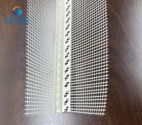
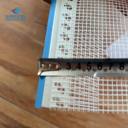


Rainwater can cling to an underside and run back toward a facade if a horizontal edge has no effective break. A PVC drip bead forms a projecting drip line that encourages water to detach at a chosen edge. Versions with attached fiberglass mesh tie the profile into a compatible reinforced render layer. The bead controls surface runoff at that location; it does not replace flashing, waterproofing, drainage, or the wall system’s moisture design.
Quick overview
Use a drip profile at an exterior downward-facing termination where the detail calls for runoff to release before reaching the underside or wall. Typical candidates include the lower edge of a projecting soffit or an appropriate head and reveal detail. Its precise position, projection, slope, and continuity must come from the architect’s detail and system supplier. A vertical corner needing a neat straight line alone usually calls for a standard corner bead instead.
What the profile does
The shaped nose creates a deliberate break in the water path. The mesh wings are embedded in base coat so the edge reinforcement connects to the surrounding layer. If the nose is buried under finish, positioned behind the outermost runoff edge, or interrupted at a joint, the drip function may be lost. A profile also cannot make water flow outward from a surface sloped toward the building; substrate geometry and drainage remain essential.
Jiangxi Ganfeng Fiberglass Mesh Co., Ltd. lists a PVC drip bead range and a mesh water drip edge. Ask for the selected profile cross-section rather than relying on a generic product photo, since the position of the drip nose governs the detail.
Where to place it
| Location | Purpose | Check before specifying |
|---|---|---|
| Exposed soffit edge | Interrupt runoff before it tracks across the underside. | Projection, slope, cover, and continuous drip line. |
| Specified window-head or reveal edge | Release water away from the reveal surface. | Flashing interface and system-approved head detail. |
| Ordinary vertical wall corner | Usually no horizontal water-release function. | Whether a standard reinforced angle is appropriate. |
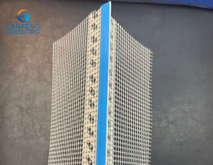
Do not put a drip bead wherever water is visible without checking where that water is meant to go. At windows, doors, balconies, and parapets, flashing and drainage design have priority. The bead should complement the assembly’s water-management path rather than divert water into a joint, cavity, or opening.
Installation and inspection points
- Set the profile at the specified outer edge and confirm the nose remains exposed after finishing.
- Keep the run straight and continuous; detail ends and joints to avoid a water bridge.
- Embed mesh wings flat in compatible base coat and overlap field reinforcement as specified.
- Check transitions with flashing, sealants, movement joints, and adjacent profiles.
- Inspect the finished slope and an unobstructed drip line before removing access equipment.
A separate alkali resistant corner bead serves corner reinforcement, but its title alone does not establish a projecting drip geometry. Compare section drawings before substituting it at a horizontal edge.
Map the water route before selecting a profile
Start at the surface that receives rain. Follow the likely path over ledges, down the facade, around projections, and beneath exposed horizontal surfaces. Water can remain attached to a smooth underside by surface tension. A shaped drip edge interrupts that path when it projects beyond the adjoining plane and remains unobstructed. The precise dimension comes from the approved detail, not a universal distance applicable to all buildings.
Draw the water route through the whole assembly. A window head may include flashing, sealant, a drainage cavity, and a rendered soffit. The drip bead can address runoff at the exposed render edge, while flashing manages water that gets behind cladding or reaches the opening. Confusing these functions can leave a concealed water path untreated. Ask the architect or system designer which component handles each route, including water entering at joints.
Assess candidate locations
Projecting soffits and undersides
A downward-facing edge beneath a projection is a common place to consider a drip break. The profile must be placed at the outer runoff edge, with enough projection to prevent water curling back across the underside. Check the upper surface slope and the continuity of waterproofing or flashing. A bead on the soffit cannot compensate for a flat or reverse-sloped upper surface that holds water against the wall.
Window heads and reveals
At a window head, runoff from the wall above needs a path away from the frame and reveal. The drawing may combine a drip profile with head flashing, sealant, and an expansion or separation joint. Confirm that the bead does not block a designed drainage opening or direct water behind the frame. Short returns at the ends deserve particular care; an otherwise continuous drip can fail where water bypasses the terminal detail.
Balconies, parapets, and other projections
These areas have different structural and waterproofing requirements. A drip bead in a render finish may help at a selected underside edge, but it is not an acceptable substitute for a balcony waterproofing termination, parapet coping, or engineered drainage outlet. Locate the actual exposure and ask which system owns the water-management detail before extending a standard soffit profile to a new location.
Specify a workable cross-section
Request a dimensioned drawing showing the drip nose, its projection relative to the finished render face, the PVC legs, and each mesh wing. State the intended coating thickness so the nose stays clear after finishing. Check whether the cross-section fits an internal or external corner and whether it is compatible with the slope and edge geometry. A photographic image can identify the general product, but it cannot substitute for the section at an unusual termination.
The mesh needs its own specification: wing widths, aperture, coating, and attachment to the PVC. For a cementitious base coat, seek appropriate alkali-resistance evidence. Confirm the prescribed overlap with field reinforcement and whether separate corner or diagonal patches are needed near openings. A product containing mesh is not a complete reinforcement drawing.
Mock up the edge and inspect it in stages
- Set the substrate to the designed slope and confirm the flashing and drainage path.
- Dry-fit the drip profile, including ends, returns, joints, and adjacent frame clearances.
- Embed the mesh wings in compatible base coat and connect them to field reinforcement.
- Apply the finish to the intended thickness without burying the water-release nose.
- Inspect continuity, exposed geometry, drainage direction, and sealant interfaces.
A controlled water observation can reveal an obvious bypass, but it is not a substitute for any specified water-penetration test. Do not flood unfinished work in a way that conflicts with curing instructions. Record the completed mock-up and use it as a reference for repeated details. Site supervision should check the profile before the final finish hides its mesh wings and attachment.
Common defects and their likely causes
| Observed condition | Possible cause | Check |
|---|---|---|
| Water tracks across soffit. | Nose buried, insufficient projection, or reverse slope. | Compare finished section and slope with the drawing. |
| Staining near a joint. | Interrupted drip line or water bypass at a return. | Inspect ends, flashing, and adjacent sealant. |
| Crack beside profile. | Insufficient mesh overlap or incompatible embedding. | Review reinforcement detail and installation record. |
| Profile appears wavy. | Uneven substrate or damage before embedding. | Check straightness and bedding before finish. |
These observations are diagnostic prompts, not proof of a single cause. Concealed water entry elsewhere in the assembly can produce similar stains. Investigate the whole detail before changing a profile. A repair that merely covers the visible drip nose with sealant may further obstruct the intended water break.
Purchasing and maintenance considerations
Order by exact profile code, drawing, length, mesh-wing dimensions, and quantity. Long PVC profiles need protection against bending or a crushed nose during transport. Check representative pieces at receipt, especially the attachment of mesh to the PVC. Retain an approved sample and identify the lot used at each elevation if project records require traceability.
After installation, keep the release edge free of accumulated paint, render, debris, or later sealant work. Periodic facade inspections should look at the whole drainage path: slope, flashing, joints, and the visible drip line. A clear bead cannot rescue failed upstream waterproofing, but a blocked nose can undermine an otherwise sound runoff detail. Maintenance instructions should reflect that division of responsibility.
Define the limits of the bead in the design note
Design notes should distinguish water shedding from water tightness. The drip profile can make exposed runoff detach at its nose, but wind-driven rain, water entering behind cladding, and moisture rising or condensing within the assembly require separate design measures. Calling a drip bead “waterproof” can obscure a missing flashing or drainage detail. Describe its location and geometric role instead.
At the transition between two materials, identify which trade installs each part and who checks the completed interface. A render contractor may set the bead while a window installer supplies flashing and another trade applies sealant. Without a coordinated sequence, a later operation may cover the release edge or leave a gap at the frame. A small approved mock-up gives all trades one reference.
Ask the project designer how ends and corners terminate. An unbroken central run can still permit water to track around an unprotected end. Some details use returns or a dedicated transition component, while others direct water into a different channel. Do not improvise the termination from a straight-profile photograph. The correct end detail depends on the assembly and adjoining components.
Before handover, photograph the exposed nose and adjacent flashing after final finishing. Include the drawing reference and profile code in the record. If later coating work changes the edge, maintenance staff can compare it with the approved condition. This simple record is more useful than an undimensioned statement that “drip bead installed” because it preserves the functional geometry.
Conclusion
A PVC drip bead belongs at a designed exterior runoff break, especially a downward-facing edge where water would otherwise track back. Select its section and location from the wall detail, keep the drip nose clear, and maintain continuous reinforcement and drainage. It is one part of moisture management, not a substitute for flashing. Jiangxi Ganfeng Fiberglass Mesh Co., Ltd. is a manufacturer and supplier with mesh-attached drip profiles; the installed assembly must still follow the project’s approved detail.
FAQ
Is a PVC drip corner bead with fiberglass mesh waterproofing?
No. It helps direct surface runoff at an edge but does not replace a waterproof barrier or drainage design.
Can a drip bead be installed on a vertical corner?
Only where the specific design calls for that profile; a standard reinforced angle is generally the relevant product for a plain vertical corner.
Should the drip nose be covered by render?
No. The functional release edge must remain clear in accordance with the profile and system instructions.
Does the mesh wing eliminate the need for field reinforcement?
No. It should connect to the surrounding reinforcement with the specified overlap.

